Solar system
Edit 4/24/2022 LRM -- not-exhaustive parts list
- Panels: Renogy 100W rng-100d
- Charge controller: BZ Products, Inc. MPPT500
- Batteries: random EverStart deep cycle (?) RV battery from Walmart
- Inverter: Samlex power 600W SA-600R series
- Automatic transfer switch: ATS: MOES Dual Power Controller 50A 5500 Watt Automatic Transfer Switch for Off Grid Solar Wind System ATS DC 12V 24V 48V AC 110V 220V
Rev. 3/16/2022 LRM
Here’s a design for a solar (power) system, which has evolved over time. Nope, it wasn’t conceived in an act of careful planning. It evolved!
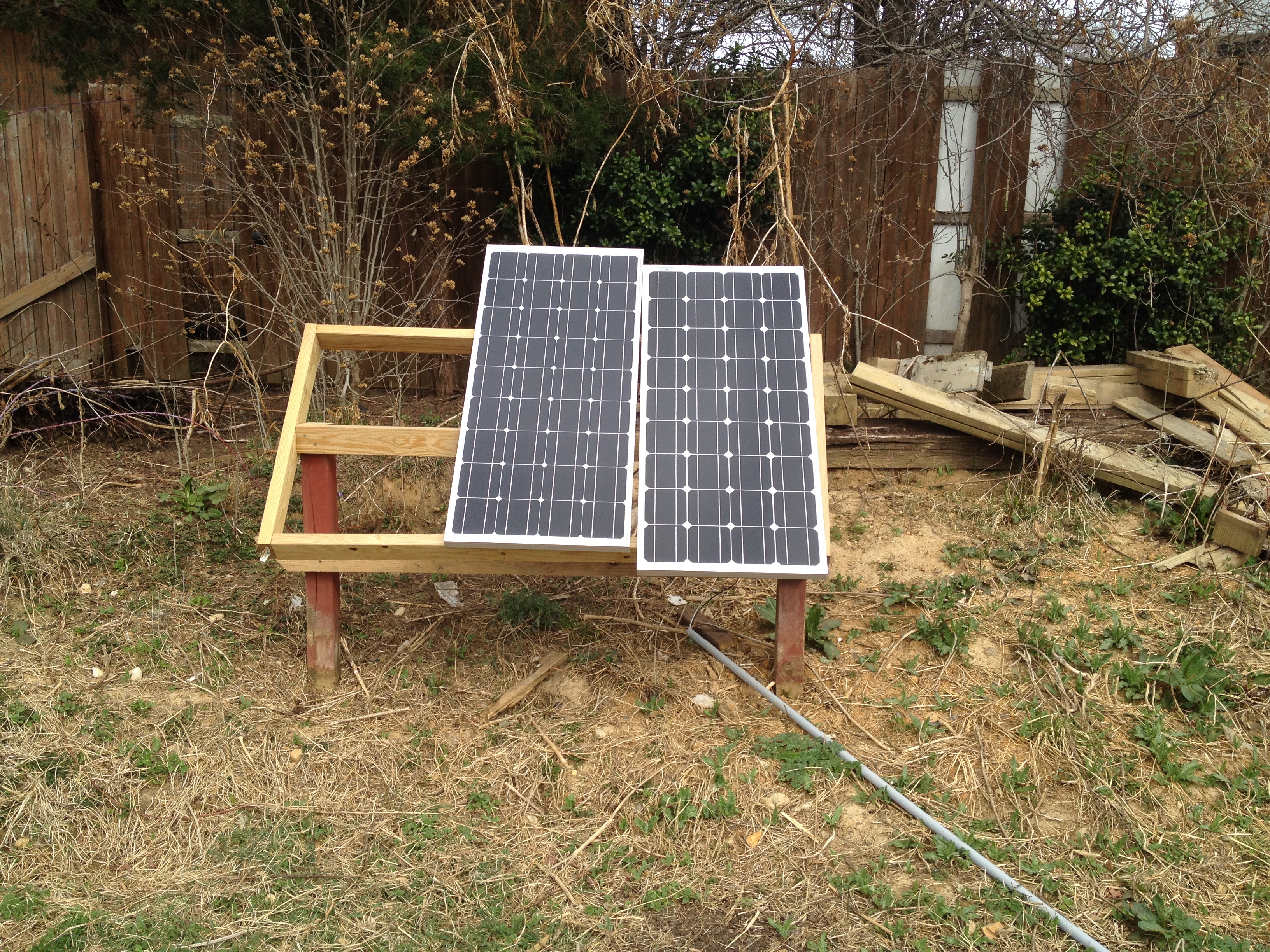
I started with one solar panel which I inherited from a friend, and I bought a second one a year or so later to increase my capacity. The frame is made of reclaimed wood from the deck. The panels are wired using basic (relatively rigid) AWG 8 wire from Lowes – not that fuzzy cable on Amazon which is “for solar panels.” IIRC the panels are 100W Renogy panels purchased through Amazon (above).
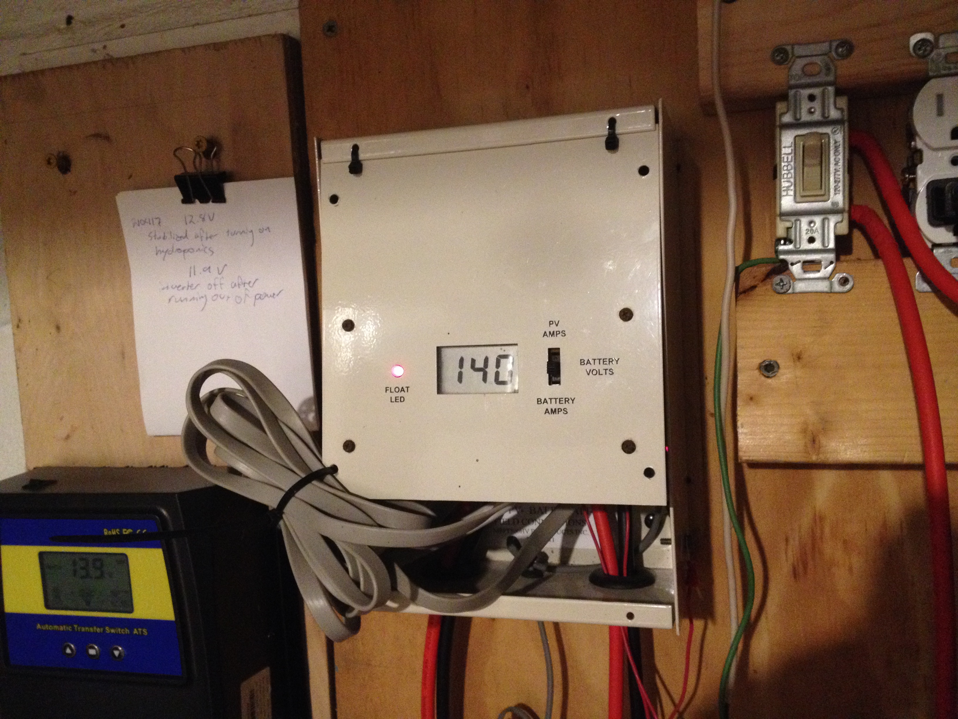
The charge controller (above) is a funny model, which I also inherited second-hand. I’m told that some dude just makes and sells these as a hobby; as such, they’re hard to find.
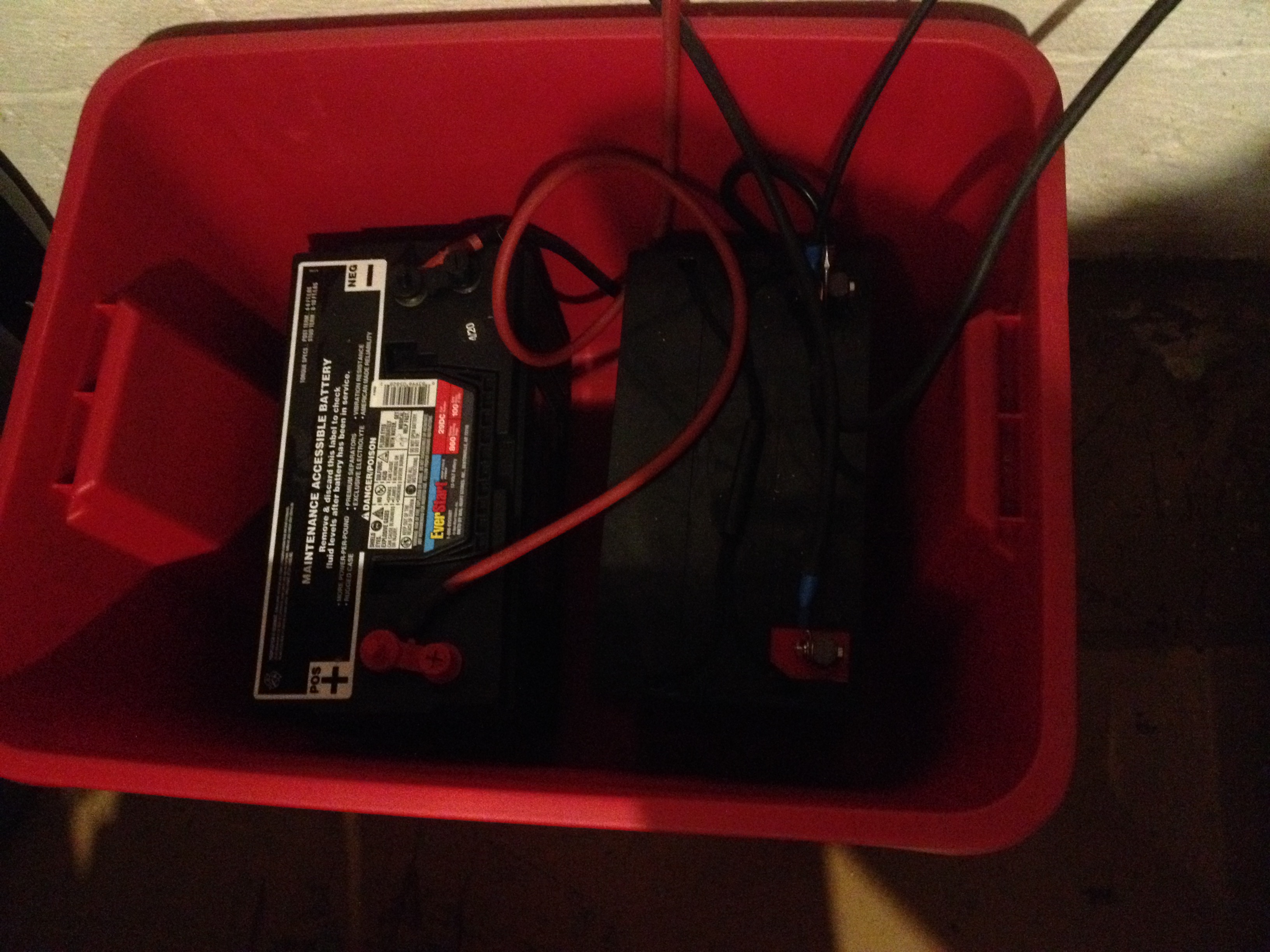
Here’s the battery tub (above). On the left is the Walmart-grade RV battery (EverStart) I am currently using, and on the right is the original battery I inherited, which no longer works very well. In fact neither of the batteries work very well. They’re wired in parallel but separated from each other by two heavy automotive grade key switches; there is only one key, so they can’t ever be connected. The batteries are housed in a plastic tote so the kitties don’t get electrocuted… I hope I remembered to put the lid back on after I took that photo!
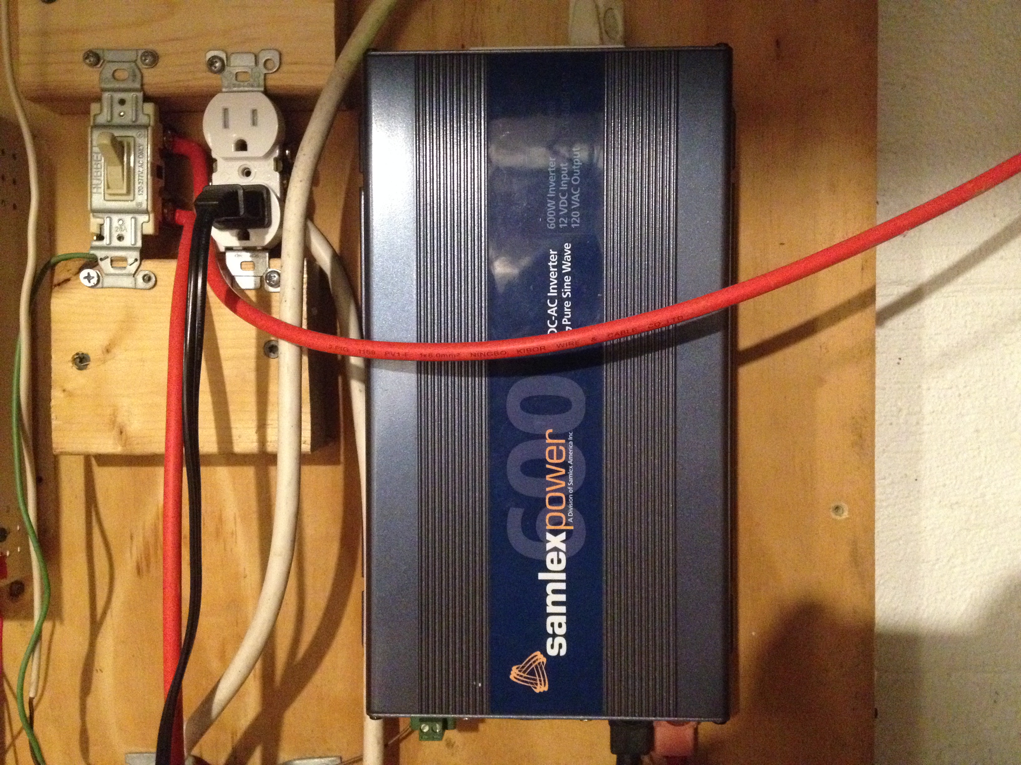
And for power conversion, I’ve got ye olde Samlex Power 600W pure sine wave inverter (above). A while ago, I got tired of it making noise to alert me to imminent power failures when the battery is drained, so I modified it to remove the beeper.
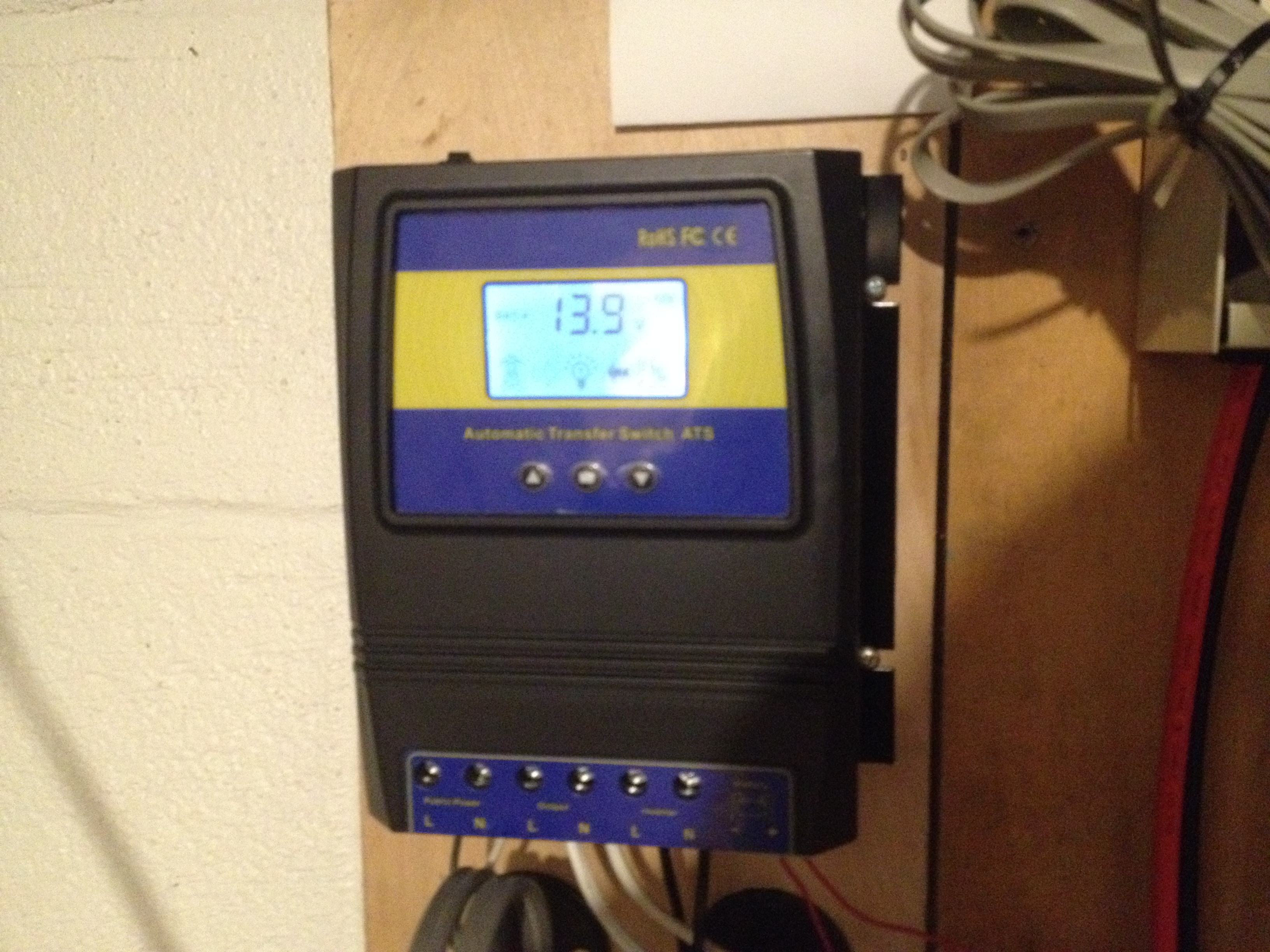
The automatic transfer switch (above) consists of a couple of beefy relays plus a micro-controller which reads the battery voltage. When the voltage is low, the relays send utility power to the output. When the voltage is high, the relays send inverter power to the output. This was about $100 on Amazon. My batteries function more as “capacitors” than as a legitimate means of power storage. When the sun goes down, the batteries usually work for a few 10s of minutes, then the system switches over to utility power. It’s worth noting that the switch defaults to utility power when the unit is powered off. This is somewhat reassuring as a protection against sending battery power onto the grid.
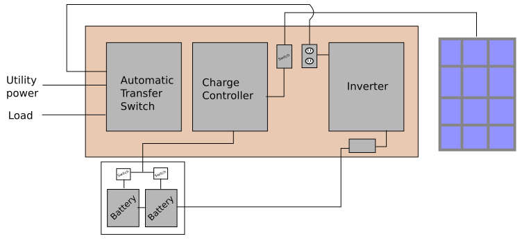
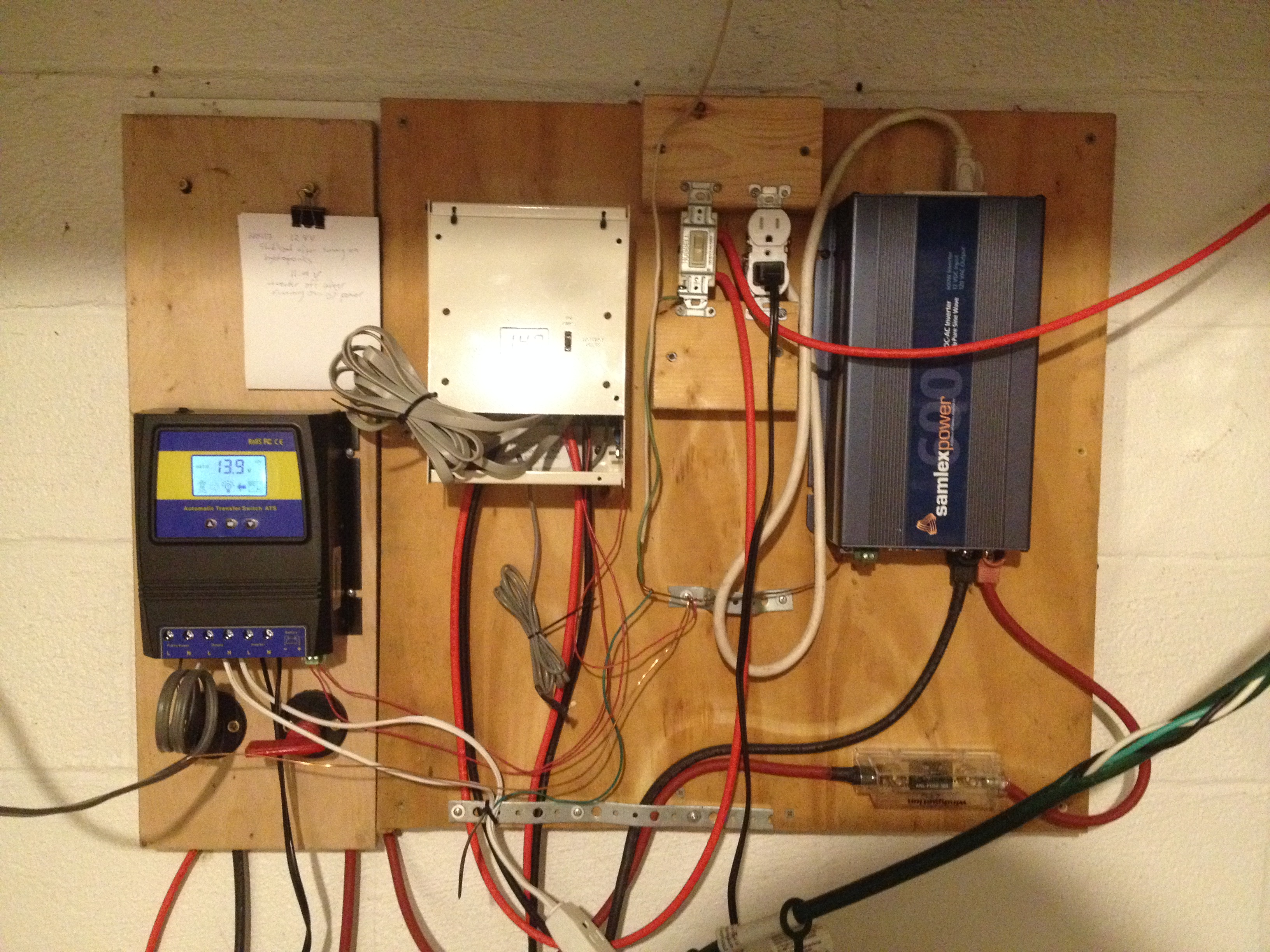
Finally, a schematic of the whole system (above). I forgot to label the little box under the inverter: it’s a fuse. Not shown is that everything is grounded to exposed copper water plumbing. The whole electronics panel -- let's call it a "working prototype" -- is shown below.